
Map Types
Studio Mapper provides multiple (and distinct) methods for face mapping. These methods are described below.
Face Maps
Studio Mapper's face maps start off with local coordinates, which are then transformed to world coordinates by georeferencing. Once georeferenced, maps appear in the 3D World view in addition to a localized map window.
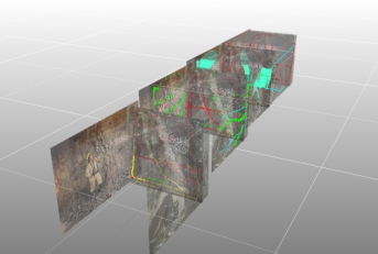
An example of georeferenced face maps in the 3D World window
Studio Mapper's simplest georeferencing method is the "1 point method". It relies on the definition of a landmark position on the map which is translated to world coordinates. In Studio Mapper, this can be done interactively, using the 3D World view.
Once a map is georeferenced, you can continue to add features to it using the Mapping task bar and a local map window; as the same map is shown in the 3D World view, any changes are automatically reflected there also. It is generally recommended to create and edit geological elements of a map using the local map window, using the 3D World view to visualize the mapped faces in their true world positions, for example, aligned with an imported mine layout design file.
Notes:
- You can re-georeference a map in the 3D window using any of Studio Mapper's georeference methods. In this situation, your control points can be picked in either the 3D or map view.
- When a map is georeferenced, the associated image file(s) are used to generated a .jpgx file. This means, providing the .jpgx file is in the same location as the image file, you can drag/drop the images into any Studio product's 3D window, and the image wireframes will be constructed at the correct world coordinates.
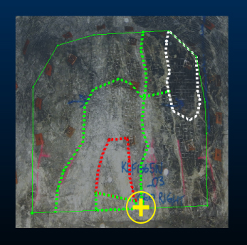
For example, the images below show two local face maps in their own local coordinate system. A few features have been digitized. Each has been georeferenced using the One Point option on the Georeference ribbon. On each map, the anchor point is shown as a yellow crosshair. Map 1:
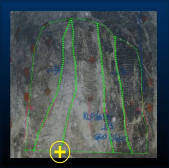
Map 2:
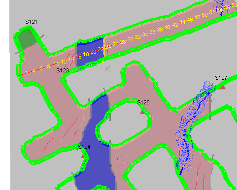
The second point (for each map) is picked in the 3D World view. In this case, each map's anchor point is translated to a snap point on a (red) drive design string:
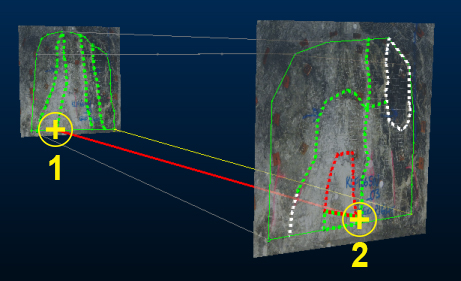
Subsequent edits to either map will now be represented in both the local map and 3D World view.
You then define the orientation of the map around this anchor point using the Rotate function (also on the Georeference ribbon), which provides an on-screen controller to adjust the orientation of the map in any of the 3 major axes, for example:
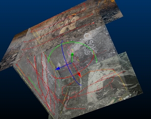
Rotation repositions the map in 3D space, and can be performed in either a 3D World view or a Map view (both georeferenced and local maps can be rotated).
Georeferenced Face Maps
Local (non-georeferenced) face maps are only visible in a Map view as they have no context in the world view yet.
Georeferenced data opens up the 3D 'global' view to see the map in its actual world coordinates, potentially alongside other georeferenced map data and "Other files". Georeferencing a face map can involve locating either one or two points, with optional interactive adjustment.
Finally, you can view the mapping 'cube' as an exploded view by choosing the butterfly map option.
Face Map and World Views
Studio Mapper will automatically swap between Map and World views to maintain a workflow.
For example, if you are working on a multi-face drive map that has already been georeferenced (say, new face data has recently become available) and you are currently working in a Map view, changing the face will maintain the same map view.
Window-swapping is performed as follows (in the table below "Local" means "non-georeferenced" and containing only local coordinates with the origin of the map in the bottom left of the front plane):
| Displayed | New item selected | Behaviour |
|
Local map, Map view |
New local map |
A map view of the local map is created/enabled. |
|
Local map, Map view |
New georeferenced map |
A map view of the georeferenced map is created/enabled. |
|
Local map, Map view |
New face on the map |
The map view is automatically rotated to a viewpoint that is orthogonal to the selected face. |
|
Georeferenced map, Map view |
New local map |
A map view of the local map is created/enabled. |
|
Georeferenced map, Map view |
New georeferenced map
|
A map view of the georeferenced map is created/enabled. |
|
Georeferenced map, 3D World view |
New local map |
A map view of the local map is created/enabled. |
|
Georeferenced map, 3D World view |
New georeferenced map (using Pick Map) |
The 3D World view is not adjusted but the design section will snap to the default face of the interactively pick (georeferenced) map. |
|
Georeferenced map, 3D World view |
New georeferenced map (not using Pick Map) |
The 3D World view is panned/rotated to look at the new georeferenced map |
|
Georeferenced map, 3D World view |
New face on the map |
The 3D view is maintained but the view is not adjusted. Instead, the design section (if previously aligned with the face) will automatically snap to the new face alignment. |
In this context, selection of a map is by any method (using a ribbon drop-down, the Mapping task bar, setting the current map using the Project Data control bar and so on).
See Setting The Current Face Map.
See Create a Face Map.
Level Maps
A Level Map (which is also supported by both 3D World and Map views) shows a single map of backs, typically accumulated over time by multiple contributors. A single plane represents the map plane, which may or may not be coincident with loaded survey data (points or strings). Map feature and other data is digitized in reference to real world coordinates, making subsequent georeferencing unnecessary.
Level maps, as a single plane, have no butterfly option.
A level map is digitized using reference data (survey strings or points) in real world coordinates.
As such, georeferencing isn't required for a level map as map data is digitized with world coordinates. This means that the 3D World view is automatically populated with level map data after it is created.
Both face maps and level maps can be viewed in the 3D World view or a dedicated map view.
See Create a Level Map.
Wireframe Maps
Wireframe maps can actually be comprised of either wireframe, point or both types of data.
A wireframe map is a 3D textured image that represents a mining surface, whereas a points map is typically a point cloud generated by survey or cavity monitor scan and supported with RGB colour information.
Wireframe surfaces for mapping can be generated either through photogrammetry, which typically yields the best textural results, or through draping images onto a wireframe. The advent of highly efficient photogrammetry software packages together with the affordability of drones has led many mining operations to capitalise on the resultant 3D imagery for mapping purposes.
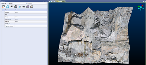
An example of a newly-loaded wireframe map type, ready for field data capture
In some cases, a detailed 3-dimensional image of each blasted face highly beneficial as it provides a visual track record of the orebody, which is especially useful in mines which employ shotcrete, where the visible rock is only exposed for a few hours until covered.
The "Wireframe" map type supports this type of mapping, and can receive data from a wide range of inputs, including lidar data or data processed by other products such as Datamine PixPro, Pix4D® and Agisoft®. Data is imported using Studio's extensive Data Source Drivers facility. As with all map types, a 3D Image map is supported by dedicated configuration file syntax.
Wireframe and points maps can be enhanced with the following map data types:
These maps don't need dimensions or georeferencing planes as the imported 3D surface determines the 'field book' for mapping. Regardless, they are still supported by both map and world window views as the former provides an unobstructed view of the surface data, which can be easier for mapping. From the 3D Wireframe Map panel, you can also clip the displayed wireframe map using Clip by Plane or Clip by String, which run wireframe-split ("spli") and wireframe-split-string ("spbs").
Note: There's no need to set up snapping modes when digitizing data (say, a polygon feature) onto a wireframe map. The closest wireframe vertex or point is snapped.
Wireframe Map Georeferencing
As a non-planar surface, you georeference a wireframe map by mapping landmark surface points to world coordinates to ensure alignment with other reference objects.
This differs from face map georeferencing where only one or two points determine the planar map location, and the map is rotated to match the appropriate dip and dip direction after. Typically, a wireframe map, once georeferenced, provides the most accurate positioning of geological 3D map features, as the map surface data aligns with a surveyed face.
Wireframe map georeferencing uses the Georeference Wireframe Map screen.
Other Ways to Change the View
All currently-available views (World or Map views) are displayed as tabs along the top of the viewing area.
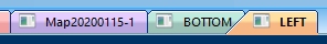
Multiple local map view tabs
A "3D" world view tab is also available (providing it hasn't been hidden by some other method). You can swap between these windows using these tabs as required.
There are also other ways to trigger a view change:
- Selecting a new map in the Mapping task bar. The response will be as described in the above section.
- Double-click or tap a face in the 3D Map view to automatically orient the view orthogonally to the target face.
- Selecting a new map using any of the Draw ribbons.
- Setting a new current map using the Project Data control bar.
- Closing a 3D view window.
- Left-clicking a map view folder in the Project Data control bar.
- Left-clicking the 3D world view folder in the Project Data control bar.
- Using the Project Data control bar's context menu system to modify a non-current map.
- Left-click the Plots folder in the Project Data control bar
- Clicking into a non-current, cascaded map view where a 3D view is concurrently displayed (the 3D view will automatically update to point to the map in the active window).
-
If viewing a 3D map, change the view from a cube-style alignment of faces or a butterfly arrangement using on-screen icons.
Note: You can only swap between 3D map and butterfly map views if your configuration permits it.
There are many options when it comes to viewing data in Studio Mapper. In projects containing multiple maps and a mixture of georeferenced and non-georeferenced maps, even more options become available.
The following guidelines may help you manage your field mapping projects.
- Capture map features in a map
view before georeferencing
You can modify map data in either a Map or 3D World view, but it is often easier to digitize features, comments, sketches etc. whilst the map view is displayed. The Map view will contain only data relevant to the current map, making it easier to focus on a particular face. - Clean your survey data before importing it for level mapping
This not only ensures a more accurate view of reference data, it also ensures that, if the Drape Mapping to Survey option is enabled, the projected shape of the digitized feature or other data closely matches the surveyed backs elevation profile. -
Use filled textures in your display templates
If you have a display template associated with a particular features object in your system configuration file, the legend can include textures. Closed/polygon structures on maps can then display a pattern overlay that can help differentiate structures, e.g.: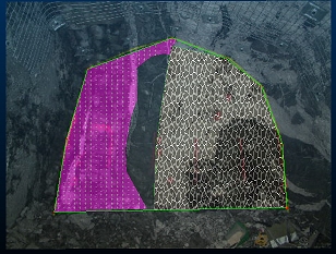
- Use clipping for multi-face maps
(drives and partial drives)
Where multiple faces exist for map, it is possible for a non-active face to partly obscure the one you're working on. Studio Mapper deals with this using smart transparency settings, but it can also be useful to clip data either side of the active plane. As the active plane is commonly aligned with the active face, clipping lets you view a face in isolation.
Clipping options are available on the 3D | View ribbon and the Navigation toolbar. - Make use of the "Pick Map"
function
The Pick Map command is available on the Map ribbon. It can be useful in a busy 3D World view as it lets you interactively pick a map to make it current and set the active section. It also automatically centers and pans the view to focus on the picked map. It's a quick way of swapping current maps in the 3D World view. - Use double-click or double-tap
to complete digitizing
You don't have to click or tap Doneto complete digitizing. Instead, you can just double-click or double-tap to end the digitizing action. This is particularly useful when sketching or digitizing map data on a tablet device. - Close a string to complete digitizing
You can complete a digitizing operation (or sketching) by closing the string, that is, positioning the final vertex at the same position as the start (commonly done using snapping). -
Wireframe map digitizing always snaps to the surface
There's no need to set up snapping modes when digitizing data (say, a polygon feature) onto a wireframe map. The closest wireframe vertex will always be the point at which a line vertex is positioned.
-
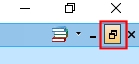
Consider using multiple cascaded windows
Where multiple georeferenced maps exist in the 3D World view, you can display it and associated Map views at the same time.If windows are currently maximized, click the Maximize toggle in the top right of the application:
You can arrange data windows so they are concurrently displayed, e.g.:
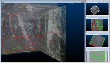
If the 3D world window is displayed, clicking into any of the available Map window thumbnails will automatically update the 3D view to show the map corresponding to the active window. This means you can make any georeferenced map current and displayed in the 3D World window just by clicking its Map window "preview". Selecting a non-georeferenced map window will not update the 3D World window.
-
If you're using a portable device at the face, enable the on-screen keyboard. If this mode is active, if you click into an editable field, an easy-to-see on screen keyboard pops up to let you tap your values directly into the system. Tap away from the keyboard to dismiss it automatically.
Related topics and activities